Caliper Brackets
The front and rear caliper brackets are constructed from the same metal stock and weld design, only differing in dimensions and hole centres, so this section applies to both front and rear brackets.
Fred Puhn states a preference for 1/2” steel, but at the front there just isn’t enough room between the vertical upright and the hub assembly to use anything thicker than 1/4” (6mm) section, so that was the start point.
The materials used were two mild steel 90deg angle sections, 6mm thick. The actual caliper mount section was from 50mm x 50mm equal section, the hub carrier/vertical link section was from 50mm x 100mm unequal section.
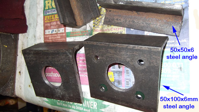
Steel angle used for front and rear caliper brackets
Although at first sight this might seem a crude choice of materials but there are a few advantages to using preformed sections.
Firstly you know that the 90 deg angle is exactly that, you no longer have to worry about setting and maintaining it through fabrication. There are bonus points in that the change in section from vertical to horizontal has a smooth blend radius, far better than any fillet weld from a design view.
Secondly the sections are accurate enough for our needs and can reliably be used as straight edge reference points when it comes to aligning the upper caliper mount section.
After the experience of making brackets for the first rear disc conversion and how difficult it was to maintain accurate alignments, the aim was to minimise distortion and use the inbuilt angles of the steel wherever practical. So the design went along the lines shown in the sketch, basically weld two angle sections together !
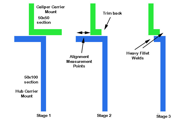
Schematic of Caliper Bracket fabrication
So all we need now is the numbers for setting the relationship between the carrier and caliper sections, and where to drill the holes to mount the actual calipers. Stage 1 is to fabricate the vertical link/hub carrier sections using the templates you made earlier and forget about the top section for the moment.
Once complete, mount this on the car and re-assemble the hub/disc because now we're going to find the vertical height for the caliper mounting holes in the 50x50x6 section steel. We're going for Dimension A in the image below. Dimension B is easy, that's directly from the caliper itself.
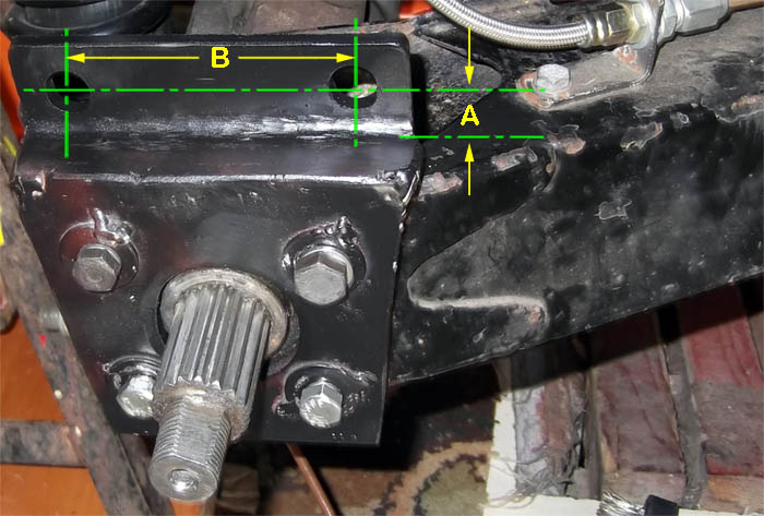
Estimating Caliper mounting position
By sliding the 50x50 steel against the lower carrier section you can get a reasonably accurate measurement of the vertical height of the caliper mounting holes on the 50x50 section.
At the front all I did was put the caliper over the disc and drop it down until the tops of the brake pads were level with the top of the disc, then mark through the caliper body holes on to the 50x50 section. To make access easier I had disconnected the steering rack which allows the hub to turn more than normal.
At the rear I’m using floating calipers and this task can be simplified by stripping the floating section away and just using the lower “U” shaped bracket that holds the sliders. The pads slip into place and it’s easy to see where you are.
To keep the hole spacing correct I used a template made from scrap aluminium taken from the caliper mounts so I only had to worry about the keeping the axis in line with the base of the L section.
Click on the button for final stages of Caliper Bracket Fabrication