
Rear Crossmember ? bent ? nah....
What do you mean the rear crossmember is knackered ? That's an original piece of Lotus workmanship and only 48 years old, why on earth would you think there's anything wrong with it ?
A Fine Piece of Lotus Engineering
But unfortunately, it's true. The poor old thing is showing it's age and when you look closely, it's definitely not right. Installed in the car it looks ok, just a bit shabby, but the straight edge reveals distortion and as you can see below, once it's out of the car then the collapse is obvious.
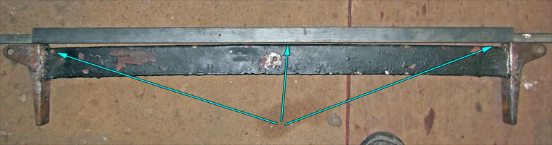
Whoops ! it's bending in the middle !
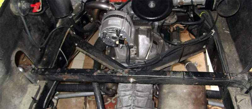
The rear cross member serves to link and transmit loading from the rear damper mounts and also to locate the two engine bay stiffening ribs. Considering the age of the car it is likely that the original dimensions were imperial units and as such initial readings were taken as Imperial and converted to metric in order to select the nearest metric plate sizes. The original brackets which are bolted to the chassis side rails were a U channel with wall thickness of 1/8”, measured at between 3.1 and 3.2mm depending on surface condition.
The crossmember also locates two stiffening ribs which are bolted centrally. This isn’t a plain hole, there is an internal crush tube to prevent the sides of the crossmember from collapsing.
Heck, it seems nothing is made to last these days, I guess I need a new one. Break out the sticking plasters....
Looking at steel suppliers I purchased mild steel in the following sizes;
Brackets : Rectangular section with 4mm wall, 80 x 40mm section (external measurements) The alternative is 3mm wall but I prefer to go slightly thicker rather than fractionally less.
Crossmember : Rectangular section with 2mm wall, 60x40mm section This is closed section and will need extra work in the centre to mount a crush tube for the stiffening rib bolt. However it will be a closed section and once rustproofed internally should last well. It will also be stiffer than the OEM.
You’ll need 0.5m for the brackets, 1m for the crossmember and there will be metal left over.
The first job is to fabricate the brackets themselves. This sketch was taken from the OEM brackets by taking a template rubbing from the originals to get the profiles and then measuring the hole positions.
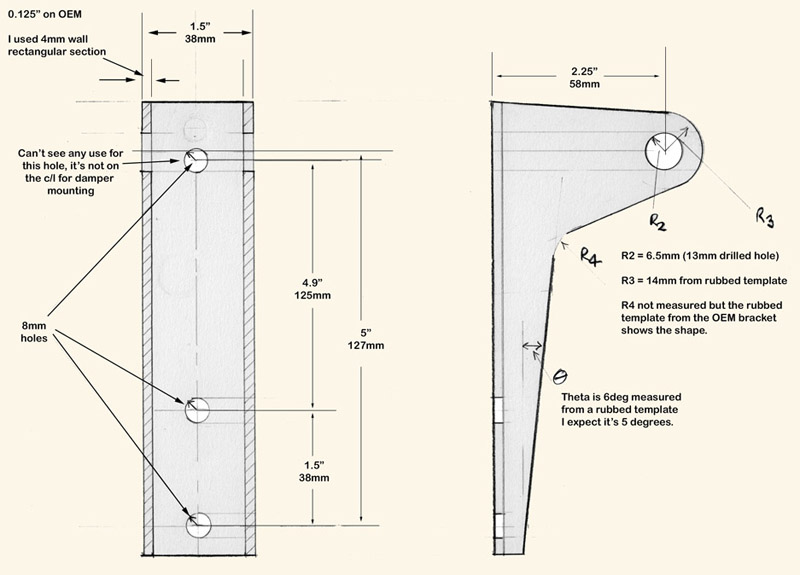
Brackets
I made a drilling jig from the OEM brackets to ensure everything is in alignment. This involves a simple 3mm plate to get the chassis mounting holes and a section of tube for the damper mounts. Bolt into place on the original bracket and then weld it together. It means damper mounts on both sides will be identical and as per the original.
But even if you don’t want to do this I’d recommend making a simple jig to align the bolt holes to the chassis for the brackets. The next image shows the crude jig in place ready to drill the chassis mounting holes with an inset of the jig being fabricated from the OEM crossmember.
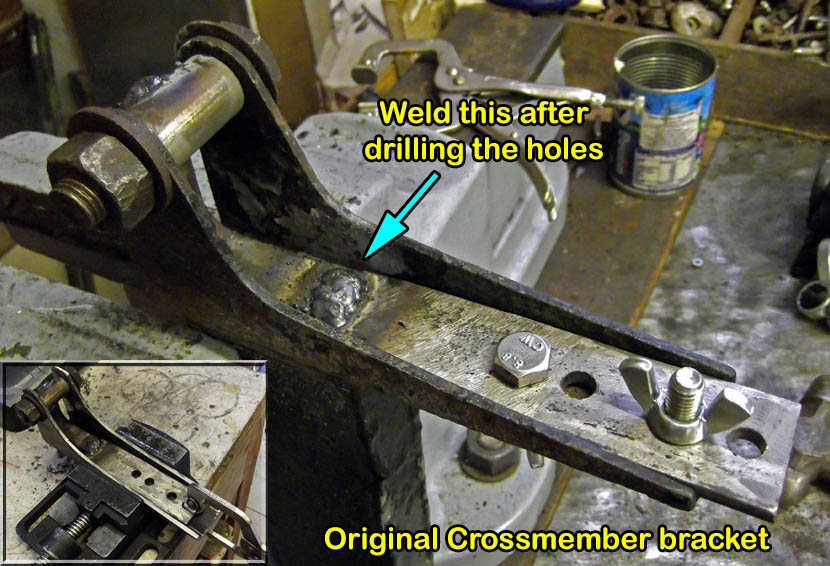
OEM bracket used to locate the important holes !
There are 2 sets of holes in this jig, the OEM settings and 0.5” away just in case I want to lower the car at any point in the future. I could lower the car by fitting shorter springs or lowering the platform on the dampers, but this method also gives me the option to leave the spring pre-load and damper travel exactly the same. It also means my new brackets are slightly longer than the originals.
As mentioned earlier, once the brackets were completed I bolted them to the chassis to measure up for the central beam.
With the engine supported on a trolley jack, the body on planks/axle stands I reckoned that was the best I could do to ensure that the chassis legs weren’t being twisted and so once the brackets were bolted into place I measured up for the rectangular central section.
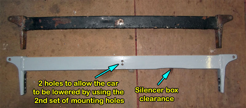
Silencer box clearance for OEM ride Height settings
I had used a deeper and slightly wider box section for the central beam. When the original ride heights are used for the brackets there’s a very tight clearance with the silencer box. Rather than hope nothing rubs when things start vibrating we might as well form a shallow recess to give better clearance rather than trust to luck.
I also incorporated 2 bushed holes in the centre for the side plates to mount to, this accommodates the potential to lower the car by raising the brackets on their second set of mounting holes later on.
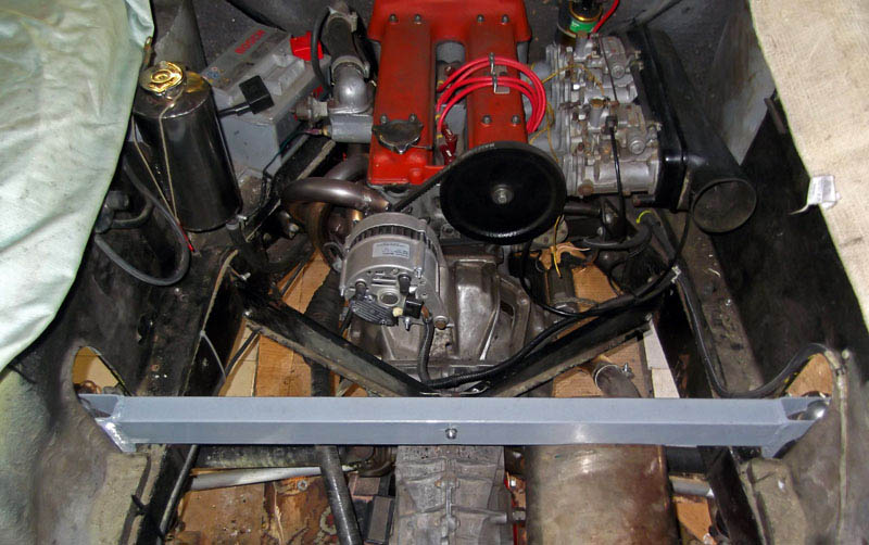
Final installation in the car
The new fabrication looks and feels a much sturdier construction than the original, plus it's something I won't have to worry about for the next 48years......
Will it make a difference to the chassis stiffness ? Who knows, in theory it should do but I’m not a skilled enough driver to appreciate it !